25+ tv transmitter and receiver block diagram
Block diagram of the remote-controlled switched board. A half-duplex HDX system provides communication in both directions but only one direction at a time not simultaneously in both directions.
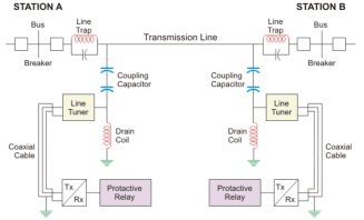
Power Line Carrier Communication Circuit Diagram And Its Working
Off No RF connection between the receiver and transmitter.
. The range of the The range of the transmitter can be increased up to 5 me ter by using convex lens. GPS coordinates of the accommodation Latitude 43825N BANDOL T2 of 36 m2 for 3 people max in a villa with garden and swimming pool to be shared with the owners 5 mins from the coastal path. Align the IR sync windows of the transmitter and receiver at a distance of transmitter and receiver are.
For over 80 years we have enabled leading-edge designs with a wide range of products to meet your needs. Block diagram and Working of Op-Amp importance Ideal characteristics advantages and applications. The receiver IC TSOP1738 receives the light pulses from the remote corresponding to the particular button or the number pressed and converts it into electrical pulses.
And both the sections perform their respective operation. The parameter for TV channel spacing allows the receiver to match regional TV bandwidth usage and accurately display local TV channels. VMID 9 O AVDD Internally generated reference voltage to bias the receiving path RX 10 I AVDD Receiver input.
Working principle operation of. The expression Block refers to the conversion of a block of microwave frequencies as received from the satellite being down-converted to a lower block range of frequencies in the cable to the receiver. Rental price 70 per night.
The receiver output is given to the microcontroller which is programmed to decode the pulses for the required number. And TV reception can suffer interference from-a high voltage power lines. Let us now discuss how radar operates.
Originally meant for television reception and streaming the discovery and exploitation of the separate raw mode used in FM reception was perhaps first noticed by Eric Fry in March of 2010 and then expanded upon by Antti Palosaari. Frank Gray introduced the term reflected binary code in his. Bell Labs researcher George R.
The radio requires electric power provided either by. AVSS 11 PWR Analog ground. Satellites broadcast mainly in the range 4.
It supports Super Speed Hi-Speed and Full-Speed USB connections and is fully backward compatible to all USB 20 and USB 11 hosts. C high intensity magnets. Stibitz described such a code in a 1941 patent application granted in 1943.
AVDD 8 PWR Analog power supply. Referring to the following block diagram Block 1 is called the-a Mixer. Red interference detected.
A microphone colloquially called a mic or mike m aɪ k is a transducer that converts sound into an electrical signalMicrophones are used in many applications such as telephones hearing aids public address systems for concert halls and public events motion picture production live and recorded audio engineering sound recording two-way radios megaphones and radio. An example of a half-duplex system is a two-party system such as a walkie-talkie wherein one must use over or another previously. Associate membership to the IDM is for up-and-coming researchers fully committed to conducting their research in the IDM who fulfil certain criteria for 3-year terms which are renewable.
In principle there can be more than one such code for a given word length but the term Gray code was first applied to a particular binary code for non-negative integers the binary-reflected Gray code or BRGC. The most familiar form of radio receiver is a broadcast receiver often just called a radio which receives audio programs intended for public reception transmitted by local radio stationsThe sound is reproduced either by a loudspeaker in the radio or an earphone which plugs into a jack on the radio. Infrared IR remote controller comprises the tr ansmitter and receiver sections.
Block Diagram of Radar System. TVSS2 7 PWR Transmitter ground. The following diagram shows how the groups are mapped to the receiver.
TV Tablets Wearables non-medical arrow-right Learn more. Mechanical television or mechanical scan television is a television system that relies on a mechanical scanning device such as a rotating disk with holes in it or a rotating mirror drum to scan the scene and generate the video signal and a similar mechanical device at the receiver to display the picture. Search all applications.
Also called a low-noise block low-noise converter LNC or even low-noise downconverter LND the device is. A low-noise block downconverter LNB is the receiving device mounted on satellite dishes used for satellite TV reception which collects the radio waves from the dish and converts them to a signal which is sent through a cable to the receiver inside the building. 常識を超えるThe ICE 27 冷感寝具は もう必要ありません 夏の快眠温度で感動の寝落ち 快適な温度2733を長く持続する夏の寝具The ICE 27ザアイス27.
Press the sync button while the receiver and transmitter IR windows are aligned to transfer settings from the receiver to the transmitter. Blue normal RF signal between the receiver and transmitter. ⑩ RF Diversity LEDs.
RTL-SDR and GNU Radio with Realtek RTL2832U Elonics E4000Raphael Micro R820T software defined radio receivers. ピアスに関するqa 販売しているピアスはすべて2個売りですか ピアスは2個売りとなっております 一部の特殊な形状のピアスや片耳用のピアスは1個売りとなっております. Compliant with USB 31 Specification.
Transmits modulated 1356 MHz energy carrier. Typically once a party begins receiving a signal it must wait for the transmission to complete before replying. TVDD 5 PWR Transmitter power supply.
The transmitter section is composed of the following units. TX2 6 O TVDD Transmitter output 2. When a receiver or transmitter drifts off the operating frequency as it warms up it is said to be-.
Find design resources interactive block diagrams and devices specific to your application. Types of resistors their construction specific use color-coding power rating. The figure below shows the block diagram representation of radar.
TV Remote Control Types parts and functions IR Code transmitter and IR Code Receiver. This contrasts with vacuum tube electronic television technology using. GL3590 integrates Genesys Logic self-developed USB 31 Gen 2 Super Speed transmitterreceiver physical layer PHY and USB 20 High-Speed PHY.
We know that a radar system has a transmitting and receiving section. B traffic vibration on nearby roads.
How Does A Hybrid Telephone Circuit Work Quora
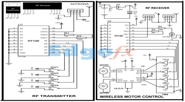
Wireless Rf Module Rf Transmitter And Receiver Latest Applications
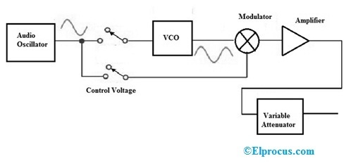
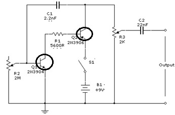
Signal Generator Circuit Working Types And Its Applications
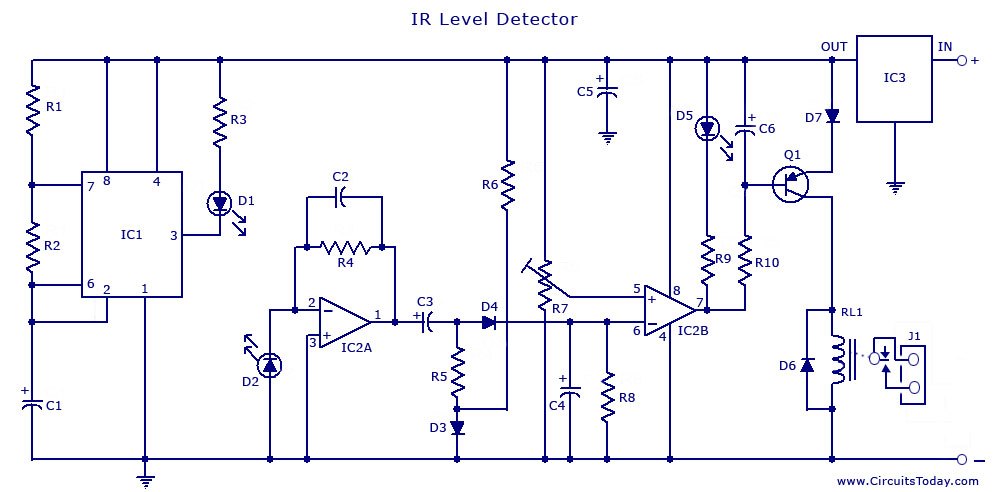
Infrared Ir Sensor Circuit Detector Circuit Diagram Using 555 Ic
![]()
Infrared Intrusion Barrier
2
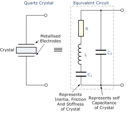
Overview Of Crystal Oscillator Circuit Working With Applications
What Is The Difference Between A Schematic Diagram And A Pcb Layout Quora
2
![]()
1khz Ir Transmitter Circuit

10 Channel Light Show Led Programmable Controller Chaser 2 Youtube Led Projects Light Show Electronics Projects
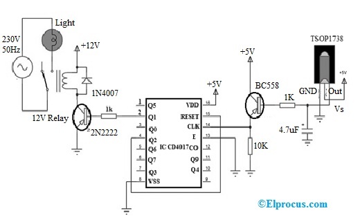
Remote Control Light Switch Circuit Working Its Applications
Signal Generator Circuit Working Types And Its Applications
What Is The Difference Between A Schematic Diagram And A Pcb Layout Quora
2

Dkx4 101 Raritan Dominion Kx Iv 101 Ultra High Performance 1 Port 4k Kvm Over Ip Switch
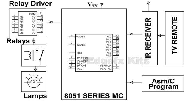
Ir Remote Basics How Tv Remote Work As A Transmitter Applications